Fuel Injector Sub-Harness
Fuel Injector Sub-Harness Guide
This guide provides an overview of the OEM fuel injector sub-harness, lists common connectors used, and outlines steps to build a new harness that replicates the OEM design.
OEM Fuel Injector Sub-Harness Description
The Honda RC51 OEM fuel injector harness connects the following sensors to the ECU:
| Sensor Name | Description | Connector Type |
|---|---|---|
| Throttle Position Sensor (TPS) | Monitors the throttle valve position. | 3-pin sealed |
| MAP Sensor | Measures manifold absolute pressure. | 3-pin sealed (same connector as TPS) |
| Injector 1-1 | Fuel injector for cylinder bank 1 (rear), primary | 2-pin |
| Injector 1-2 | Fuel injector for cylinder bank 1 (rear), secondary | 2-pin |
| Injector 2-1 | Fuel injector for cylinder bank 2 (front), primary | 2-pin |
| Injector 2-2 | Fuel injector for cylinder bank 2 (front), secondary | 2-pin |
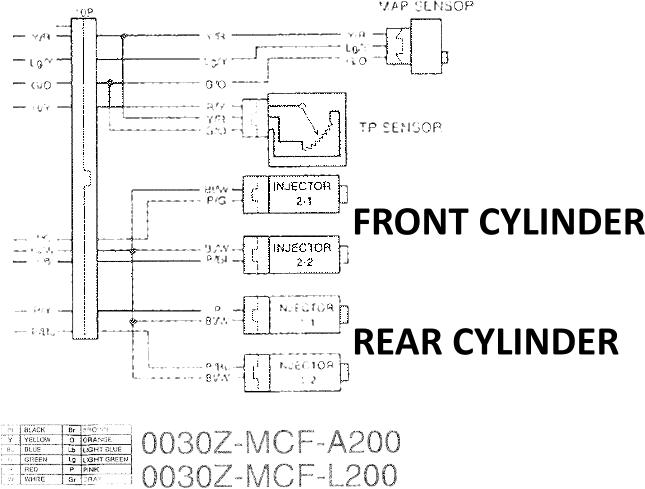
It should be noted that on the wiring diagram, Honda considers the rear cylinder as cyl #1, and the front as cyl #2. This is seen physically on the sub-harness where the rear injector connectors have the label '1' on them. This is unusual, since the firing order is front-rear, usually you would label the first fire as cylinder #1, but based on my research and the Service Manual Honda had different plans. This leaves me in a bit of a conundrum, personally I want the front cylinder to be cylinder 1 and the rear cylinder 2. So, MAKE NOTE OF THIS, that is what I am going to do on the ECU side. In the FT ECU, cylinder 1 will be front and cylinder 2 will be rear. I will try to refer to them as front and rear whenever possible to avoid confusion. Just know that if you see my documentation elsewhere that I will refer to the cylinders (their numbering) the opposite to that of the way Honda did. If in doubt, refer to them as FRONT and REAR.
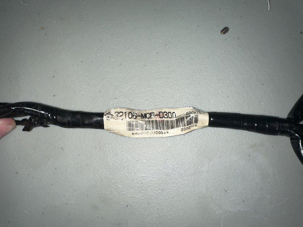
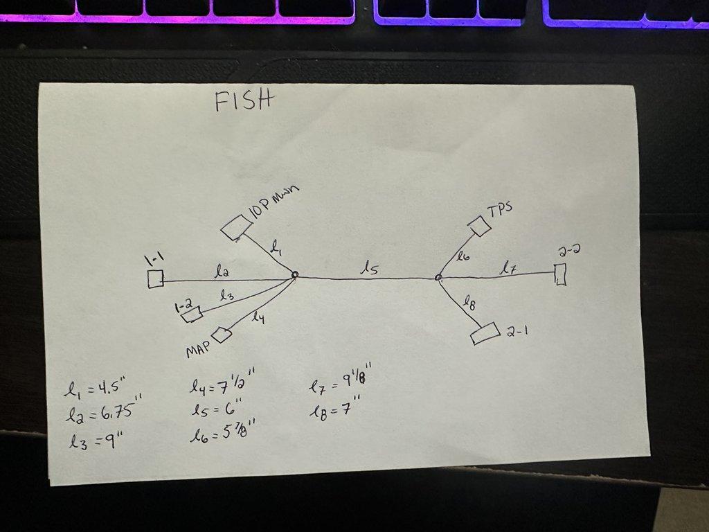
Here is the OEM wiring diagram snippet outlining the fuel injector sub harness:
OEM vs Custom Sub-Harness
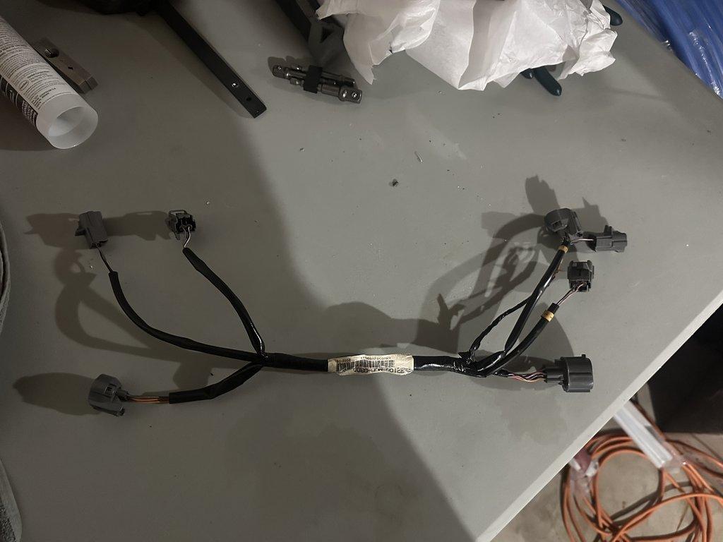
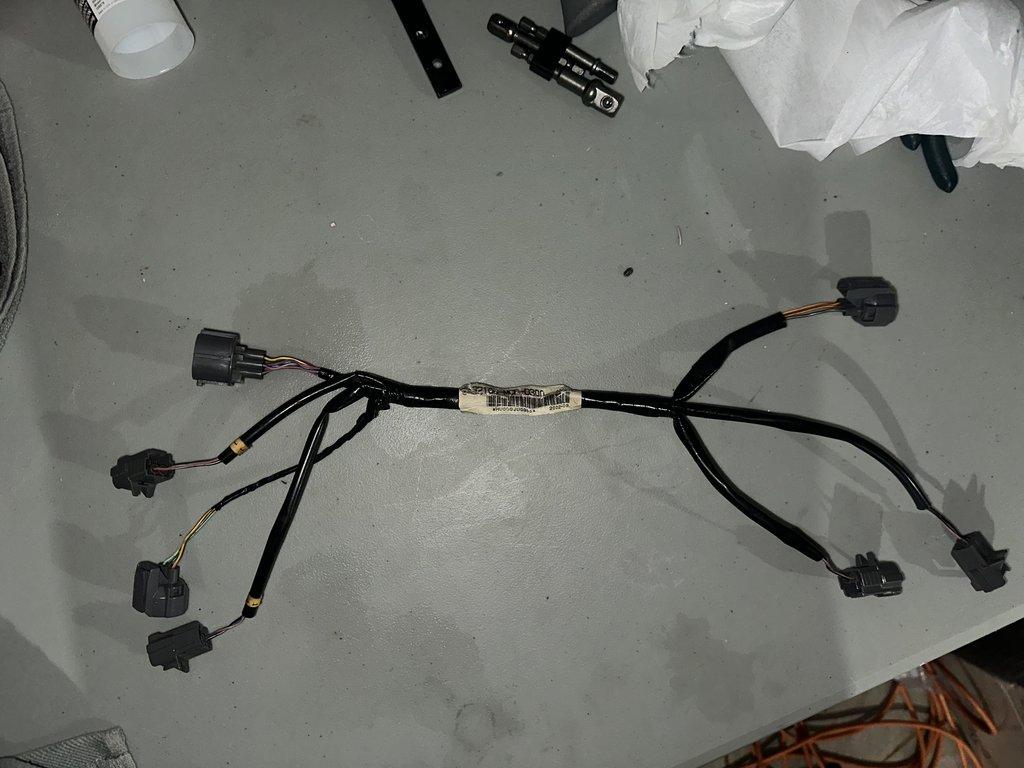
I decided to re-use the OEM fuel injector sub-harness for this project. I did not see any applicable reason to create a custom harness for the injectors. However, I did go through the trouble of identifying all of the connectors on the harness so if you decide you would like to create one, you can do so. Check out the individual pages for the TPS sensor and injectors for more information on the connectors those components use and where to source them.
Using the OEM harness, I would just leave the MAP sensor connector unplugged as I used the internal MAP sensor on the FuelTech ECU and just ran a vacuum line from the location where the MAP sensor was connected up to the ECU. I also decided to attach the fuel pressure sensor at a different location on the main harness so I could reuse OEM injector harness. That and this harness sits under the air box, making it a bit difficult to have the connector for the fuel pressure sensor on this sub harness unless the wires were long enough to not limit being able to prop the gas tank up.
Main Connector on the Harness
Like mentioned previously, check out the individual pages on the TPS and injectors for more information on the connectors those components use. This page only covers the 10-pin sub-harness connector that connects this sub-harness to the main harness.
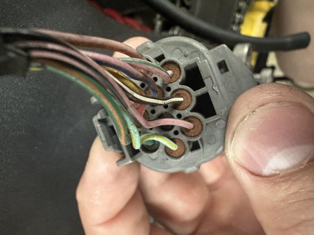
Here is the main OEM connector pin layout for this sub-harness:

The following is the pinout of the OEM FI harness as well as color code:
| Pin Location | Color | Use | Wire Gauge |
|---|---|---|---|
| 1 | Yellow/Red(stripe) | +5V | 20 |
| 2 | Red/Yellow(stripe) | TPS Signal | 22 |
| 3 | Green/Orange(stripe) | Sensor Ground | 20 |
| 4 | Pink | Injector 1-1 (Rear Primary) | 22 |
| 5 | Pink/Blue(stripe) | Injector 1-2 (Rear Secondary) | 22 |
| 6 | (none) | empty | (none) |
| 7 | Light Green/Yellow(stripe) | MAP Signal | 22 |
| 8 | Pink/Green(stripe) | Injector 2-1 (Front Primary) | 22 |
| 9 | Black/White(stripe) | +12V | 20 |
| 10 | Pink/Black(stripe) | Injector 2-2 (Front Secondary) | 22 |
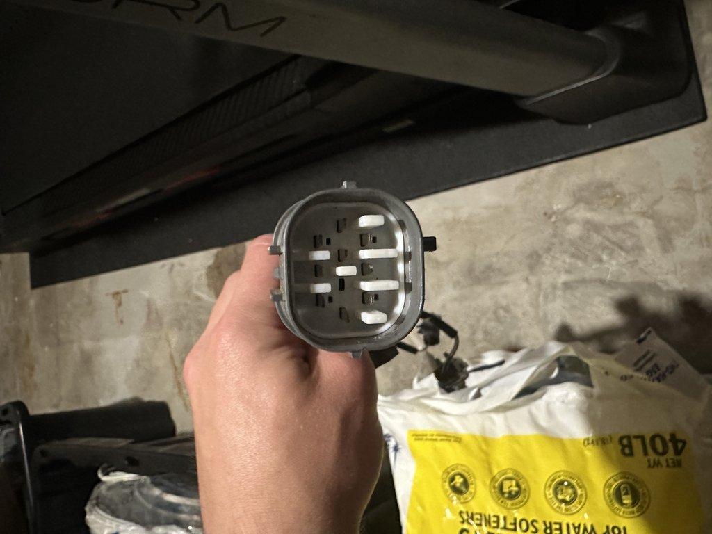
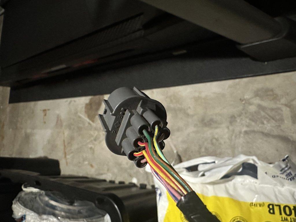
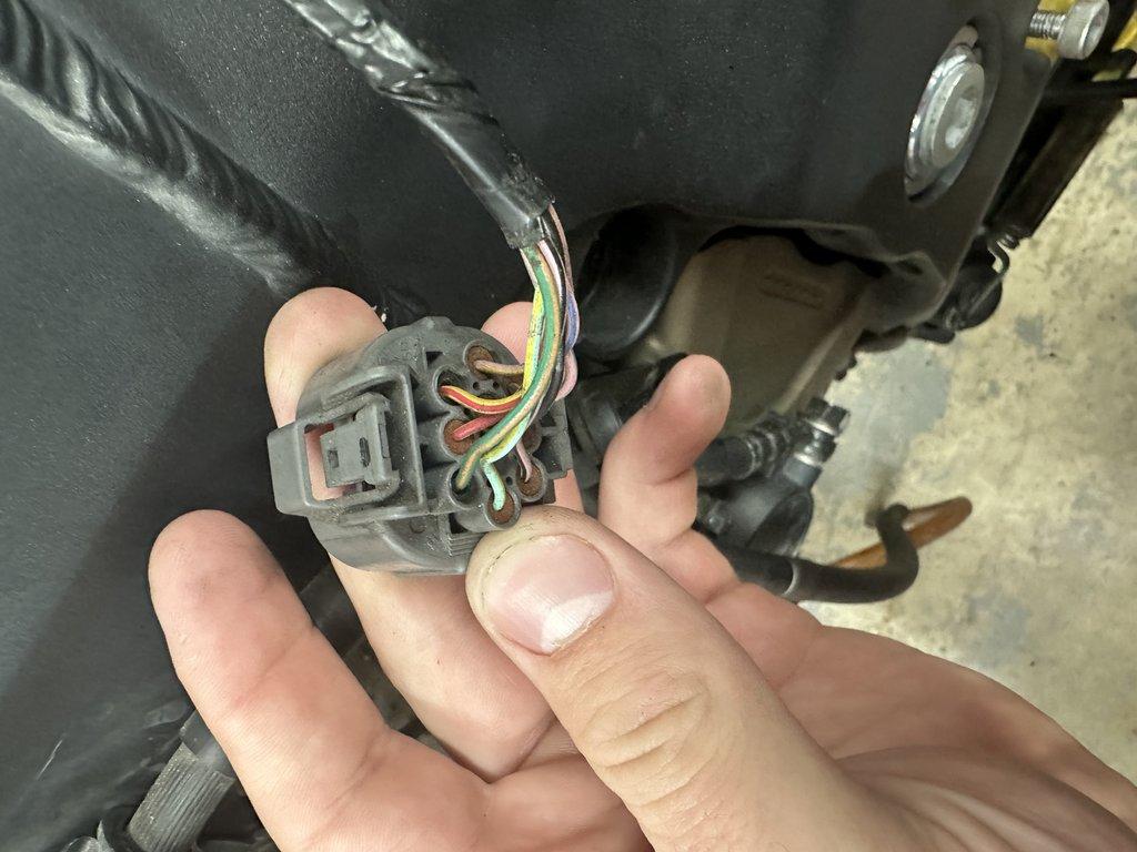
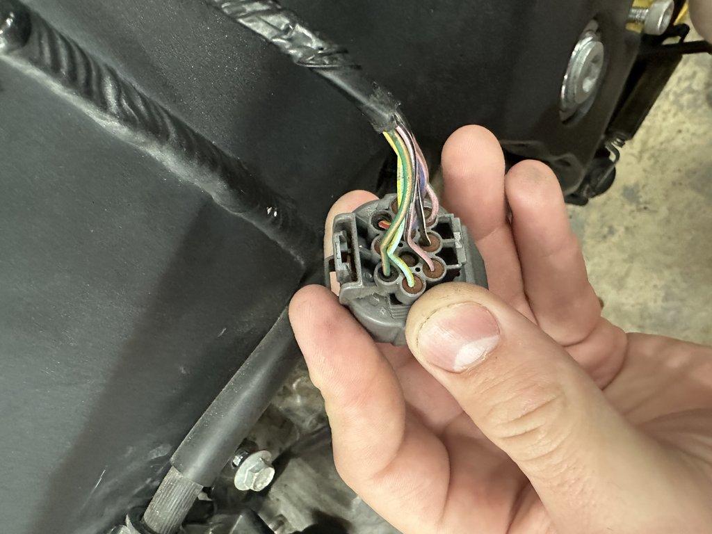
For reference, here are some images of the physical male connector that is located on the FI sub-harness:
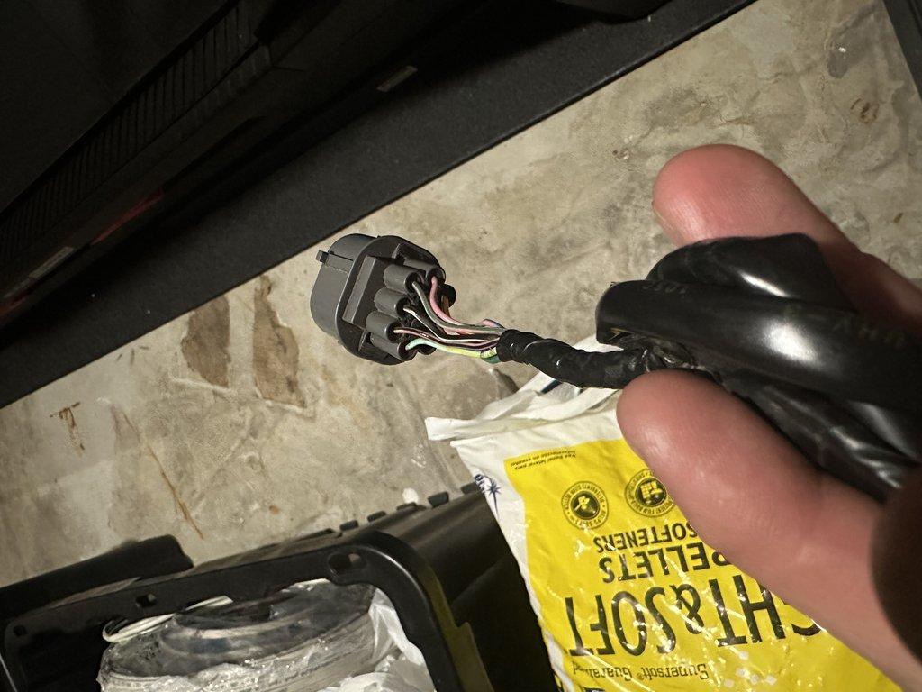
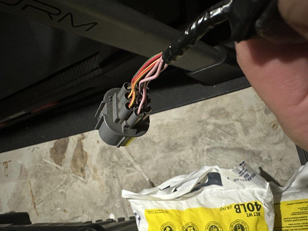
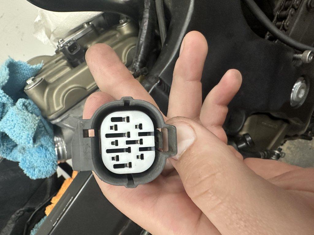
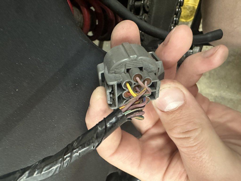
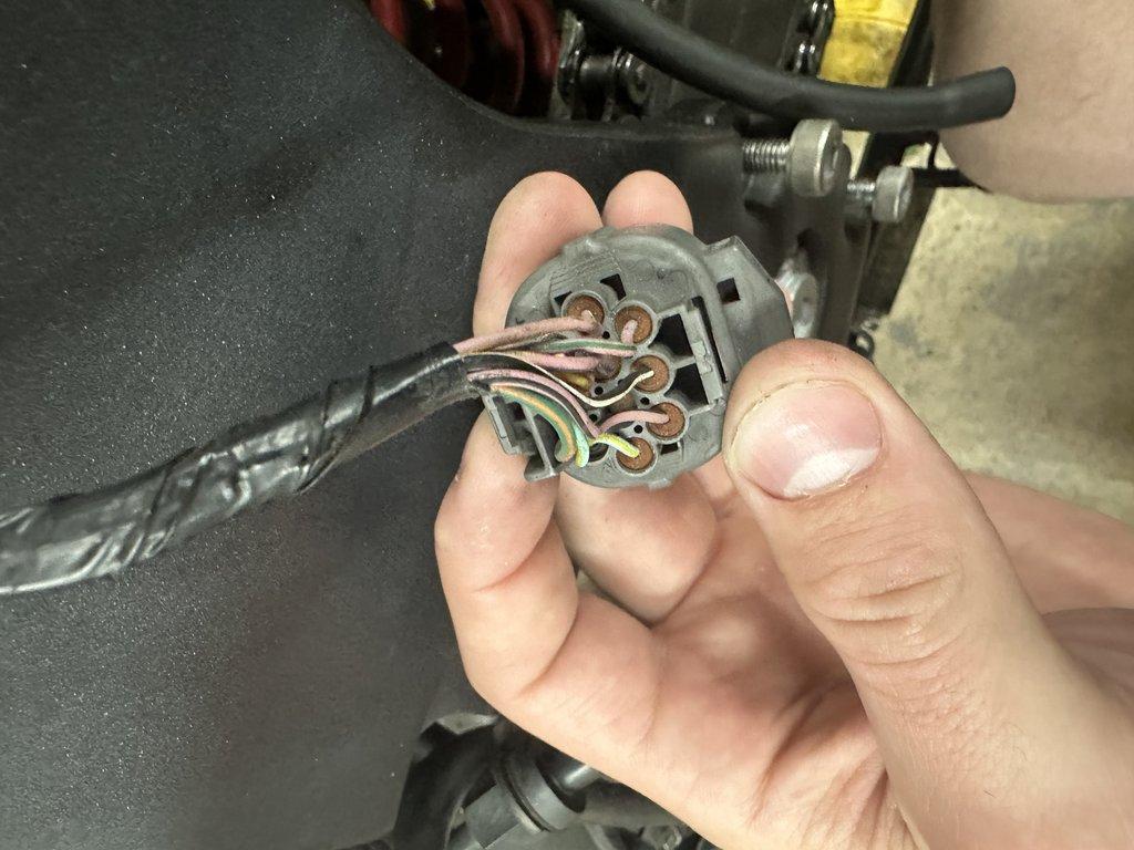
Here are some images of the physical female connector that is located on the main harness and the actual housing that you will need to source for your new main harness:
Sourcing the Main Connector
This connector is a Sumitomo HW Sealed Series, 10 pin. Refer to the table below for data on the male and female connectors. If you are using the oem FI sub-harness, you need the connector that is on the oem main harness, which is the female housing.
| Way | Sumitomo Part Number | Model | Info |
|---|---|---|---|
| Male | 6181-0076 | HW-10P | Info |
| Female | 6189-0135 | HW-10S | Info |
Misc Data
The information in this section is impocmplete, use at your own risk. I will update it soon.