Throttle Position Sensor
This page provides detailed information about the Throttle Position Sensor (TPS) used in the Honda RC51, including its specifications, connector details, visual references, and technical documentation.
TPS Description and Ohm Readings
The Honda RC51 employs a single Throttle Position Sensor (TPS) mounted on the throttle body to monitor the throttle valve position. The TPS is a potentiometer that sends a variable voltage signal to the ECU, indicating the throttle opening angle, which is critical for precise fuel delivery and ignition timing. The TPS is connected via the fuel injector sub-harness.
Measuring the resistance (ohm readings) of the TPS is essential for verifying its functionality. Using a multimeter across the sensor terminals, the expected readings are as follows:
| Measurement | Resistance (Ohms) | Notes |
|---|---|---|
| Between VCC and GND (total resistance) | Approx. 5.05 kΩ | Measure at room temperature (approx. 20°C / 68°F). |
| Between Signal and GND (variable) | Approx. 0.870 kΩ (closed) – 5.07 kΩ (open) | Varies with throttle position; fully closed to fully open. |
These ohm readings serve as a reference. The TPS should be calibrated in FT Manager during the setup of the base tune to ensure accurate performance.
Connector Data
The TPS on the Honda RC51 uses a Sumitomo 3-pin connector integrated into the fuel injector sub-harness, which is the same connector type used for the MAP sensor. The table below provides specific TPS and connector details:
| Property | Details |
|---|---|
| Connector Type | Sumitomo 6189-0154, HW Sealed Series (3-pin) |
| Pin Configuration | Pin A: +5V (VCC), Pin B: Signal Output, Pin C: Sensor Ground |
| Wire Gauge | Pin A: 20 AWG, Pin B: 22 AWG, Pin C: 20 AWG |
Proper pin assignment is critical for the TPS, as incorrect connections can lead to erratic ECU readings. Always verify pin assignments using the Honda RC51 service manual to ensure correct connection to the sub-harness. Refer to the FI Sub-Harness page for a detailed wiring diagram.
Sourcing the TPS Connector
The TPS connector can be sourced from the following reputable suppliers:
- Cycle Terminal - 3-pin HW - .090 Female Connector
- KSV Looms - SKU: OE10835
- Corsa Technic - Connector Specifications
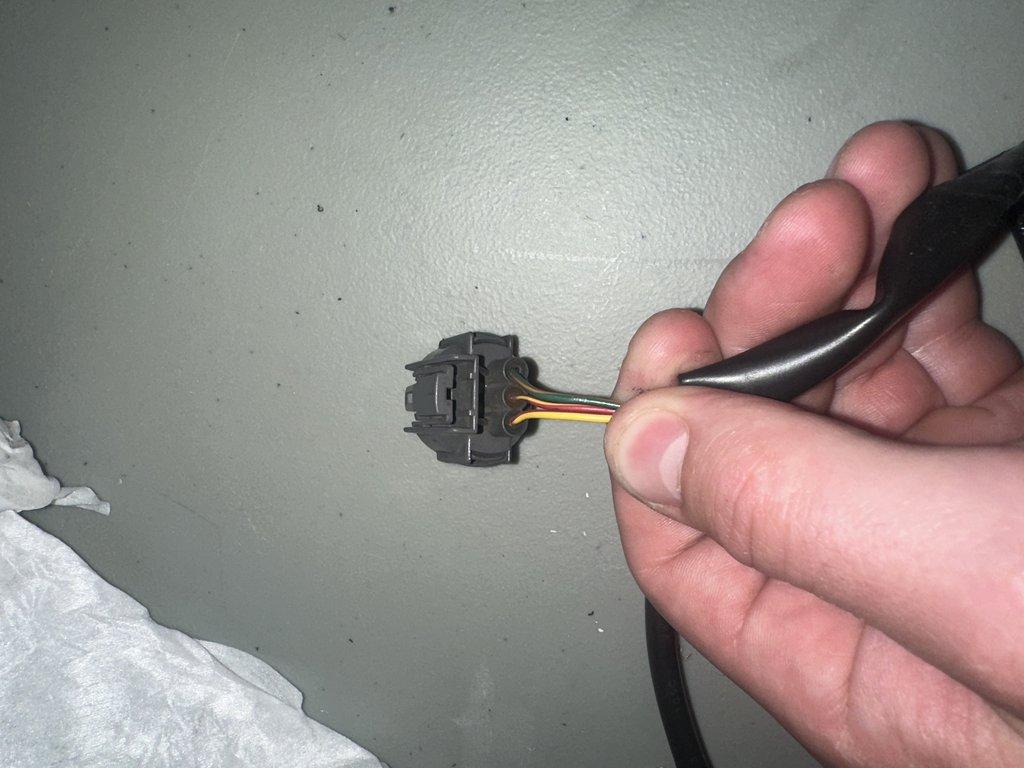
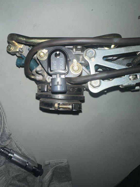
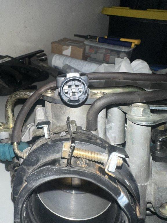
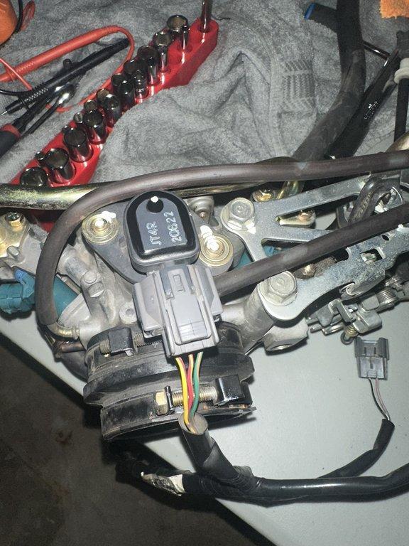
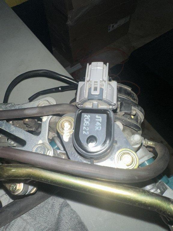
Throttle Position Sensor Images
Explore this collection of high-resolution images showcasing the Honda RC51 Throttle Position Sensor. These visuals provide detailed views of the sensor body, connector (pin and seal sides), and the TPS with its connector attached.

Wiring Diagram
Refer to the OEM FISH or the Custom FISH for detailed wiring details.